Programming the 16F84a Microcontroller using Linux
Introduction
The 16F84a Microcontroller is basically a computer within one small microchip. It is one of hundreds of similar chips made by a company called Arizona Microchip.
Their website is vast and contains an overwhelming amount of information about these chips.
These chips can be programmed to perform operations based on the chips inputs and outputs. For example you could program one to measure the temperature of a room and turn on a heater if it gets cold. Actually this is a pretty complex task, so this page will explain how to do something more simple - make an led flash on and off.
What you need to get started
To use these chips you need two pieces of hardware and two pieces of software
Hardware
1. The Hardware Programmer
2. The circuit to test the put the chip in once it has been programmed
Software
1. To write and compile assembly (.asm) code to a hexadecimal (.hex)
file
2. To burn the hex file onto the chip
1. The Hardware programmer
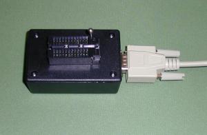
This is the piece of hardware that connects the chip to the serial port (or sometimes parallel port) of your computer. You can buy on of these for around £100. But I found that they can sometimes be tied to DOS software and are therefore not very Linux friendly. A much cheaper alternative is to build your own. This sounds a little daunting, but after many hours on the web I managed to find one that was really simple, and costs less than £5 to build.
This programmer was designed by Mark Colclough, you can find details of how to make it at:
http://www.cm.ph.bham.ac.uk/software/yappa/hardware.html
If you are at Access Space you will be able to use one that I have already built, it should be around somewhere and looks like this.
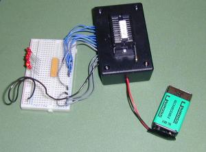
2.The test circuit
Once the chip has been programmed, the following
hardware is needed for the microcontroller to function.
A 32KHz timing
crystal and 2 68p capacitors to send clock pulses to the chip
A 5 volt
power supply (This is done by using a 9 volt battery and a L7805CV
A
0.1u capacitor
1 470R resistor
1 LED
The circuit we are going to use is taken from a book called;
PIC in practice by D.W.Smith The circuit diagram is on page 6
I think it is a pretty good book on the subject, although it is based on using PC software. The book and all of the examples in it can be found at www.bh.com
Again if you are at Access Space you can use the the test circuit I have already made which looks like this.
Software
Now that all of the hardware is in place we will concentrate on the software. There are basically two pieces of specialized software required to program the microchip.
1. Writing and compiling assembly (.asm) code to a hexadecimal (.hex) file
The language we are going to use to program the chip is Assembly. If you look at books and websites about programming PICs, you will also find that they are often programmed with basic. I avoided this as I thought that it would make the process of achieving results with Linux a little more complex because Basic has to be compiled to Assembler (another area for things to go wrong).
Assembly can be written in any text editor, but it needs to be compiled with a compiler. I used Yappa software for this.
The great thing about Yappa is that it simultaneously edits and compiles Assembly, and troubleshoots it.
It also burns the file to the chip, but we will come to that later.
So now to write the assembly program. Open Yappa from the command line by writing ' Yappa '
This example is taken from the PIC in Practice book I mentioned earlier
It looks pretty terrifying but for now we only really need to look at the sections in bold.
;HEADER.ASM FOR 16f84a. This sets PORTA as an INPUT and
PORTB as an OUTPUT
;port. It also sets the OPTION to /256 to give
timing
;pulses of 1/32 of a second.
;1 second and 0.5 second
delays are included in the
;subroutine section
tmro equ 1 ;TMR0 is
FILE 1.
porta equ 5; PORTA is FILE 5.
portb equ 6; PORTB is FILE
6.
status equ 3;STATUS is FILE3.
zerobit equ 2;ZEROBIT is Bit 2.
count equ 0x0c ;USER RAM LOCATION.
;**********************************************************************
org 0;0 is the start address.
goto start;goto start!
;**********************************************************************
;
SUBROUTINE SECTION.
;1 SECOND DELAY
delay1 clrf tmro;START TMR0
loopa movf tmro,w;READ TMR0 IN W
sublw 32;TIME - W
btfss
status,zerobit;CHECK TIME-W=0
goto loopa
retlw 0;RETURN
AFTER TMR0 = 32
;.5 SECOND DELAY
delayp5 clrf tmro;START
TMR0
loopb movf tmro,w;READ TMR0 IN W
sublw 16;TIME - W
btfss
status,zerobit;CHECK TIME-W=0
goto loopb
retlw 0;RETURN
AFTER TMR0 = 16
;****************************************************************************
;CONFIGURATION
SECTION.
start bsf status,5;Turn to BANK1
movlw 0x1F;5 bits of
PORTA are I/Ps.
tris porta
movlw 0
tris portb ;PORTB IS
OUTPUT
movlw 0x07
option;PRESCALER is /256
bcf status,5;Return
to BANK0
clrf porta;Clears PORTA
clrf portb;Clears PORTB
;****************************************************************************
;Program
starts now.
begin bsf portb,0;Turn ON B0.
call delayp5;Wait
0.5 seconds.
bcf portb,0;Turn OFF B0.
call delayp5;Wait 0.5
seconds.
goto begin;Repeat
END;You MUST END.
These examples are based on the ones in the PIC in Practice book. As this workshop is an overview I can't go into detail about the how the code works so I would highly recommend reading it to understand the code.
Try writing and testing some more examples. Try changing the subroutine delayp5